Electrical control system
PCB Design
InwZaBoard

For lnwZaBoard we design it to manage the stage of the robot and hub of all device connection.This board will mount on base of the robot and connect to driving system board.There are 7 parts as follows
Power source for electrical control board
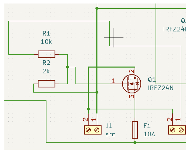
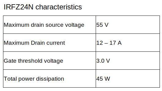
Power MOSFET (Q1)
Before electrical power will connect into other components, electrical power from source (J1) must be through the power MOSFET (Q1) which is controlled by SWboard (J2) at the panel. SWboard will send voltage signals directly from the battery which signal voltage between 20-30V. So this signal need to use voltage divider (R1 and R2) to make signal to 5 V at the gate pin of the MOSFET
Lets R1 fixed to 10 k𝛺 , set Vin to 30 V. and Vout change to 5 V.
\[\begin{split}R_{2} = \frac{V_{out} \times R_{1}}{V_{in} - V_{out}} = \frac{5 \times 10000}{30 - 5} = 2000 \Omega \\\end{split}\]If we set R2 to 2k𝛺 , Vout when Vin is 20 V. is
\[V_{out} = \frac{V_{in} \times R_{2}}{R_{1} + R_{2}} = \frac{20 \times 2000}{10000 + 2000} = 3.3 V\]So when we use R1 at 10 k𝛺 and R2 at 2k𝛺 , Vout will divided to 3.3 - 5 V. for gate threshold voltage
Protection fuse (F1)
After electrical power pass through the MOSFET(Q1) . circuit muse be protection system in order to protect over current and short circuit. So we use 10A 250V fuse to protect in this section.
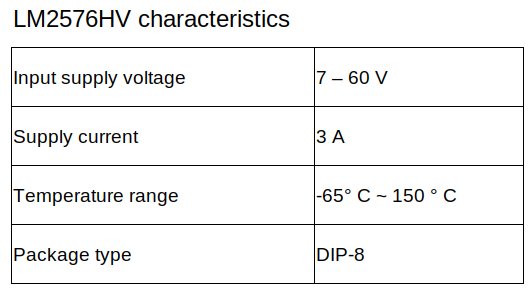
Buck converter circuit (LM2576HV)
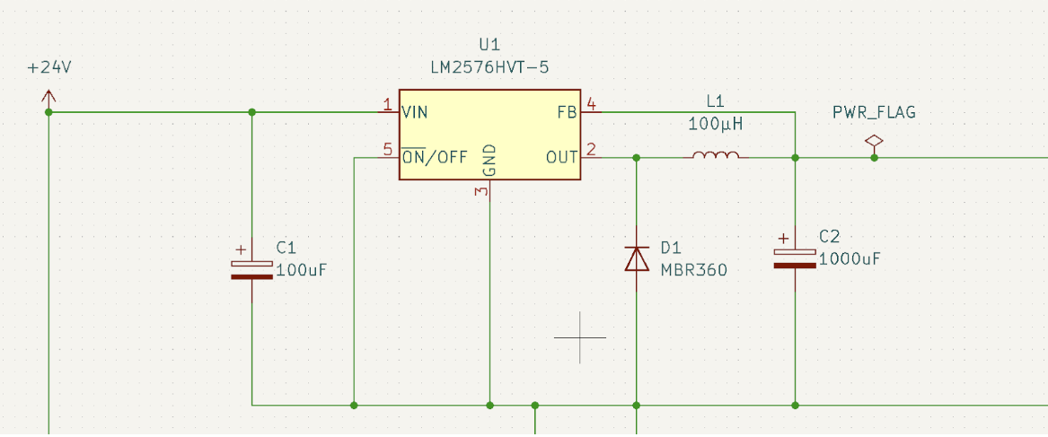
Component selection
From datasheet , it suggested that
C1 must be 100 uF , 75 V. Aluminum Electrolytic
C2 must be 1000uF, 25 V. Aluminum Electrolytic
D1 must be Schottky diode (MBR360)
L1 must be 100uH 4.4A (7916N-101M)
From this circuit , we will get a buck converter circuit that supply constant voltage at 5 V. and maximum current at 3A
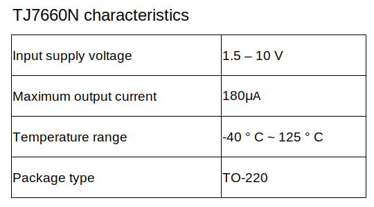
Charge pump circuit (TJ7660N)
In order to Op-amp need a negative voltage to function. So we choose to implement a charge pump circuit using the TJ7660N charge pump voltage converter IC that is used for converting positive constant voltage to negative constant voltage.

Component selection
From datasheet , it suggested that
C4 must be 10 uF , polarized capacitor
C5 must be 10 uF , polarized capacitor
C6 is 4.7 uF polarized capacitor as a bypass capacitor in this circuit
From this circuit , we will get a charge pump circuit that supply constant voltage at - 5 V. for connecting with Vss of Op-amp
Lidar sensor and Coil contact Hub

This part contains 2 mosfets that control contactor coil and supply electricity to Lidar.This contactor coil will supply the electricity in part of Body and Base of robot.
Op-amp circuit

This part is design to amplify voltage signals from resistor chants that give 0-0.75mV to 0-3.3V for the amp meter to enable measuring current.
RJ45 port

This part is the RJ45 port for connecting 2 user buttons,Emergency button and Start button.We use RJ45 for easy connection and maintenance.
Control Panel port

This part contains 4 mosfets that control the pilot lamp for display state of the robot,GPIO pin port for switch mode of operation and GPIO pin port for Power transmission of the base device.
External Panel

There are 4 functions at the panel of the robot.
Current sensors : it is used for measuring the current of the entire robot.
Selector switch : It is used to turn the robot on and off
Indicator lamp : It is used to show electrical status of the robot
On - off switch : It is used to turn the electrical control system on and off
Selector switch and Indicator lamp

Selector switch A : A is the selector switch that controls the contactor at the body of the robot which will have a green indicator lamp shown at the panel.
Selector switch B : B is the selector switch that controls the contactor at the base of the robot which will have a blue indicator lamp shown at the panel.