Experiment
Electrical Load Testing (Full load)
From calculation, we know total load when robots operate at full load. So we designed this experiment to test actual load when robots operate in typical applications.
Experimental design
robot operating time = 4 hrs.
robot inertial remaining battery = 25.6 V
robot calculated average current = 30A (remove UR3e and motor from load calculation)
Desired result from experiment
Real robot rated current
The relevance between battery voltage and robot operating time.
Result
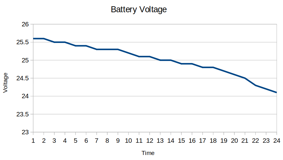
In case of battery voltage, the robot operates at full load mode. In 4 hours, battery decrease about 1.5 V. by voltage characteristics of this graph according to NMC characteristics graph which becomes linear when a single battery cell has voltage between 3.75 - 3.55 V. (with multiple cell will be at 26.25 - 24.85 V)
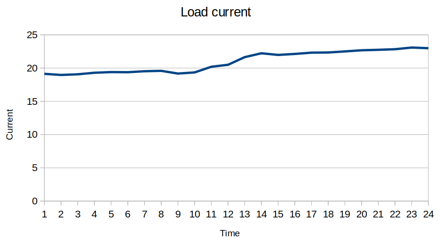
In the case of robots, they operate in full load mode. Robots will set current to constant at 19 A. but in watt’s law, when devices supply a constant power. When voltage decrease depend on battery , current will be increase instead.
Electrical Load Testing (Standby load)
From calculation, we know total load when robot operate at standby load. So we designed this experiment to test actual load when robot operate in typical application.
Experimental Design
robot operating time = 4 hrs.
robot inertial remaining battery = 27.72 V
Robot calculated average current = 2.5A (remove UR3e from load calculation)
Desired result from experimen
Real robot rated current
The relevance between battery voltage and robot operating time.
Result
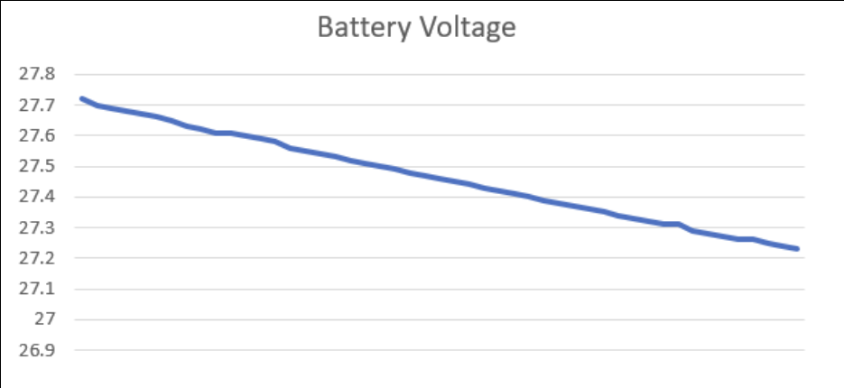
In case of battery voltage, the robot operates at standby mode. In 4 hours, battery decrease about 0.51 V. by voltage characteristics of this graph according to NMC characteristics graph which become linear when single battery cell has voltage between 4.15 - 3.75 V. (with multiple cell will be at 29.2 - 26.25 V)
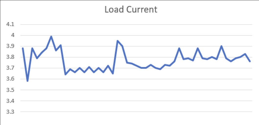
In the case of robots, they operate in standby mode. Robots will drain current between 3.6 - 4 A. because some devices drain current unsteady such as Intel NUC. So the average current in this experiment is 3.77 A.
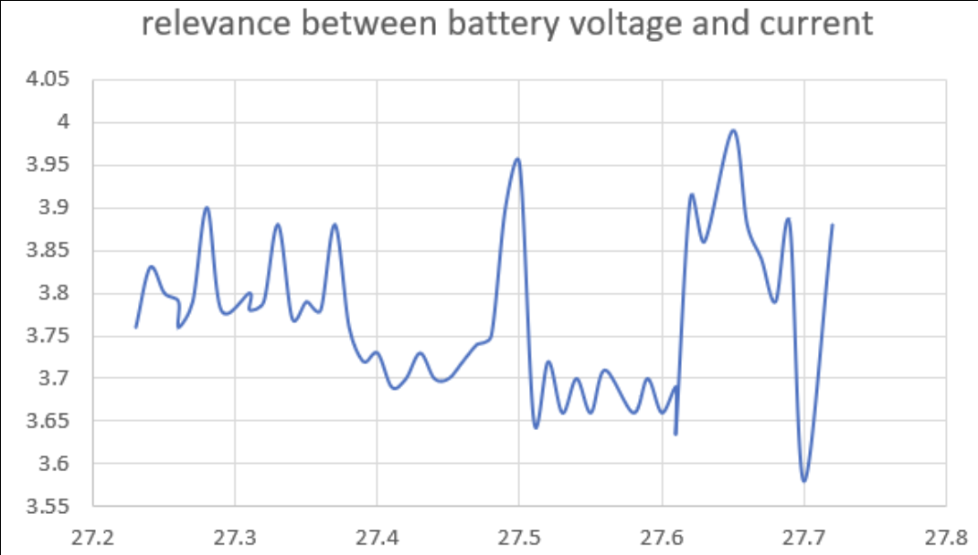
When we compare between battery voltage and load current, it is considered that current will be increased when battery voltage decreases. Because devices drain load at constant power.
Linear Load calculation
Calculated current load = 2.5A.
Initial voltage = 27.72 V.
Operating time = 4 hours.
Charging Load Testing
From calculation, if we charge the robot when the robot’s remaining battery is about 10-20% , the charger will precharge at a small current. Then the charger will charge at constant (40A) when battery resistance is a value that can be charged. Finally when the battery capacity is almost full (80-100%) the charger will charge at constant voltage (29.2V). So we designed this experiment to test actual current when the robot is charging in each period.
Experimental design
robot remaining battery voltage : xx.x V
Max charger current : 40A
Desired result from experiment
Real Charging time.
Charger behavior in each period.
Real charger current during charge.
Result